
In this article, we explain the well known term of deep foundation in marine structure or in a dam, what is diaphragm wall, how to construct diaphragm wall, equipment required to construct, types, and design consideration as per IS code.
So, Before going to start my one request to you is, if this article is useful and informative than please share with your friends and also join our telegram group to get such information as soon as possible.
Table of Contents
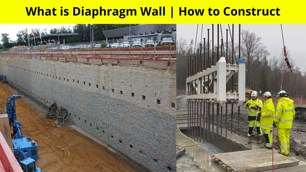
What is Diaphragm Wall
Diaphragm wall is a continuous earth retaining structure which retain the soil or doesn’t allow soil to collapse. It is subjected to heavy earth pressure thereby causing a heavy overturing movement at the foundation.
Diaphragm Walls (D-Wall) are used for various purposes such as,
- Impervious Wall in Dam
- Earth retaining structure in basement
- Earth and water retaining structure in jetty and other marine structures
- Subways
- Wells
- Bridge Foundation
- Quay Walls
- Dry Docks and Locks, etc.
Normally, The width of diaphragm wall for impervious cutoff wall is 100 to 200mm and for structural member is 450 to 1200mm.
Diaphragm walls of 1m thickness have successfully been built in soft clays of density about 1.5 t/m2 and 65m depth in india.
Before going to understand the construction procedure of diaphragm wall, let’s understand the few terminology related to diaphragm wall.
Also Read: What is Slurry Wall Construction | Process | Full Details
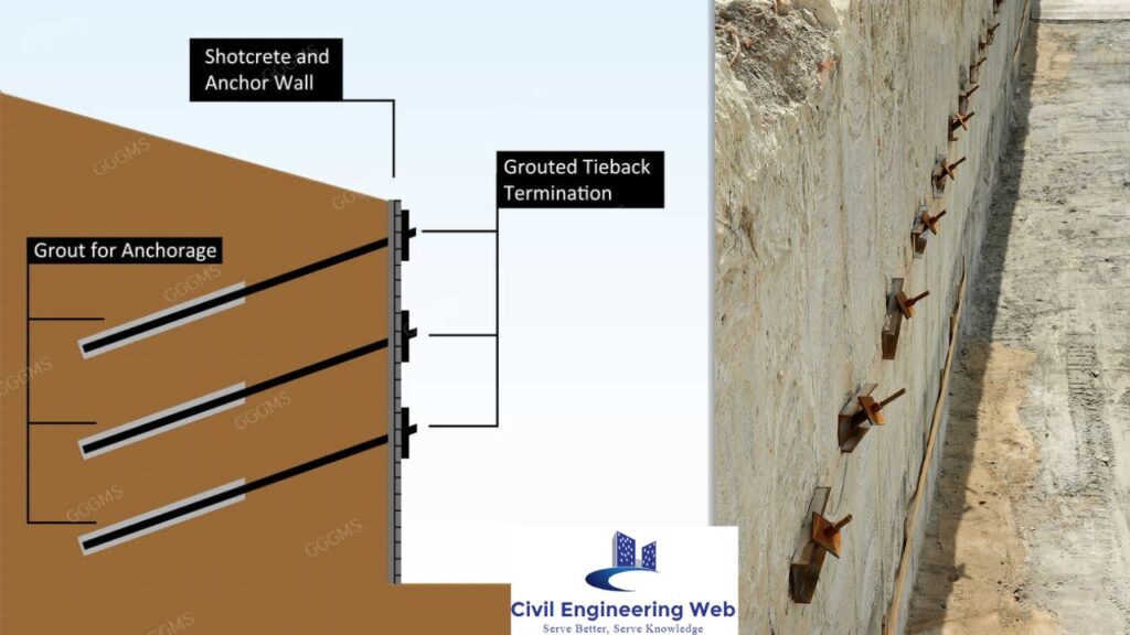
Anchorage
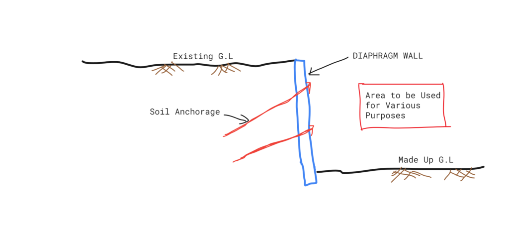
The structure that is used to anchor the D-wall with other surface or medium to carry the lateral thrust of wall is known as a Anchorage in diaphragm wall. Generally, ties to a series of concrete blocks or a continuous RCC beam, vertical or battered piles inclined rock or soil anchors are used for this purpose.
Bentonite
Bentonite is a clay formed by alteration of volcanic ash and rich in montmorillonite clay mineral. Bentonite has exchangeable irons on the surface of particles. It swells in the presence of water and its suspensions are thixotropic.
Also Read: 7 Best Methods of Dewatering | Procedure | Necessity
Panel
Panel is defined as a unit trench/wall excavated or cast at a time.
Guide Wall
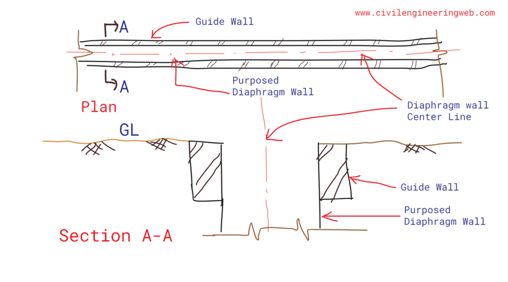
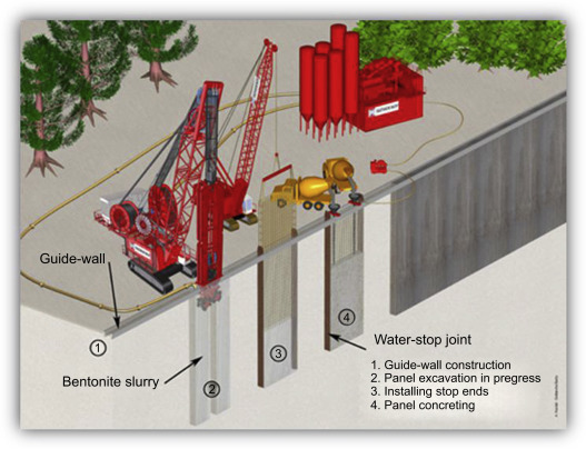
Guide wall is nothing but a shallow depth wall constructed on both side of diaphragm wall to guide the grabbing equipment for creating trench of diaphragm and prevents collapse of trench panels. Its contain Bentonite Slurry.
Tie Rod
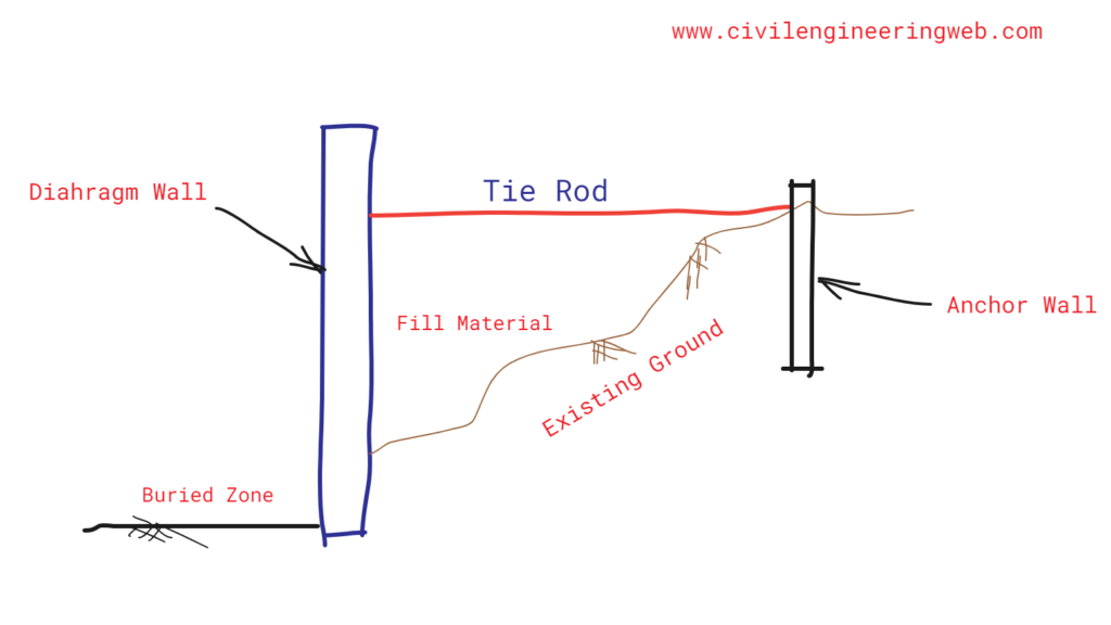
Tie rod is a structural steel bar used to transfer the earth pressure on the wall to the anchorage.
Shore Line
A line at which water level is zero and the bed level is more than zero.
How to Construct Diaphragm Wall
The construction of diaphragm wall includes the few procedure in sequence. But before going to understand the construction procedure, let’s know the few information that is necessary before design and construction of diaphragm wall.
Necessary information for construction of diaphragm wall
The following information is generally necessary for the construction of D-wall.
- 👉 Site Plan, Detailed Drawings showing different views, elevations and sections along with necessary details of nearby structure.
- 👉 Detail Subsoil Investigation Report
- 👉 Physio-chemical and engineering properties of sub soil
- 👉 Ground Water Table, Flow condition of Ground water table.
- 👉 Estimation of acid radicals of the soluble salts in the water, pH Value
- 👉 Estimated load during construction and in permanent position
- 👉 Maximum and minimum water levels , velocity of currents, scour action, wave heights and wave action of hydraulic structures or walls near river banks, reservoir or sea front, etc.
- 👉 Size, weight, capacity of trenching and concreting machinery
- 👉 Working principal of trenching and concreting machinery
- 👉 Availability of local materials
- 👉 Details of auxiliary construction machines like lifting cranes, tower cranes, etc.
- 👉 Existing Under-ground services.
Also Read: What is Timbering
Material to be required in construction of diaphragm wall
- Cement : The cement shall be used as per local and ground condition. But mostly Ordinary Portland cement or Rapid Hardening Portland cement is used in construction.
- Aggregate : Normally, 20mm size well graded coarse aggregate shall be used in reinforced diaphragm wall. For plain concrete, plastic concrete or grout walls, a similar size of aggregate may be used.
- Sand : Well graded sand consisting 50% coarse sand shall be used.
- Water : Clean water shall be used which is free from deleterious impurities. Water used for preparation of bentonite slurry shall be free from salinity and other deleterious impurities.
- Admixture : Chemical admixture shall be used in concrete as per their requirement and purpose.
- Reinforcement : Mild, Deformed, Cold or steel section conforming to respective standards shall be used. All reinforcement shall be clean and free from mill-scales, dust, rust, oil, grease, paint, or other coating which may reduce the bond with concrete.
- Concrete : The Water/cement ratio of used concrete shall not be greater than 0.6. The slump of the concrete used shall be 150mm to 200mm for good workability and easy to flow in tremie pipe.
- Bentonite : Sodium based bentonite shall be used in preparing bentonite slurry. For saline and chemically contaminated ground water condition, the slurry may be suitably processed with chemical..
Equipment Required in construction of Diaphragm wall
The following equipment’s are required to complete the construction procedure of diaphragm wall.
- Trenching Equipment: Suitable trenching equipment’s are chosen based on site condition, type of soil, depth of diaphragm wall, length and thickness of D-wall, local availability, etc. Trenching equipment include the rotary boring rings, percussion boring rings, trenching bucket type shovel, mechanical grabs, hydraulic grabs, grabs with Kelly bars, grabs controlled by suspended wire ropes of a crane, submersible mortar drills, etc.
- Slurry Preparation and Testing Equipment: Tanks of suitable sizes and slurry pumps of suitable capacity should be used for storage, mixing and circulation of bentonite slurry at a site.
- Concreting Equipment: Concrete Mixers, Tremie pipes of suitable length and size and concrete pouring devices shall be used for various concreting purposes as per their need.
- Lifting Devices: Cranes of suitable capacity and boom length should be used in the case of precast wall panels for lowering them in the trench. Also, the reinforcement cages of large depth and length of wall panels may be lifted by crane, derrick or any other suitable auxiliary rig.
Also Read: 7 Types of Crane Mostly Used in Construction
Stages of Diaphragm Wall Construction
Construction of diaphragm wall consist the following stages:
- Marking of Center Line
- Construction of Guide Wall
- Excavation of Panels
- Inserting Reinforcement Cage
- Concreting
1. Marking of center line
This is the first stage of d-wall construction in which a marking of center line and fixing the position of d-wall done by appropriate survey.
2. Construction of Guide Walls
Next stage consist the construction of guide wall on both side by keeping space of d-wall. Mainly, its construct to guide the excavation of panels operation for diaphragm wall.
Normally, Guide wall shall be 100 t0 250mm thick, 1 to 2m deep and made of lightly reinforced concrete. In soft ground or fill, guide walls may be taken deeper.
When ground water table is close to surface, guide walls higher than the surface level shall be constructed to maintain additional slurry head. For heavy machinery, guide wall shall be constructed with suitable ground slab on both side of the D-wall.
3. Excavation of Panels.
This stage includes the removal of soil from panels area to construct diaphragm wall. The Clamshell or Grab equipment is used to excavate soil from panels area. If any obstruction is encountered, it is broken by the means of a gravity hammer and taken out by means of the grab.
Also Read: Different Exposure Condition for Concrete as per IS 456
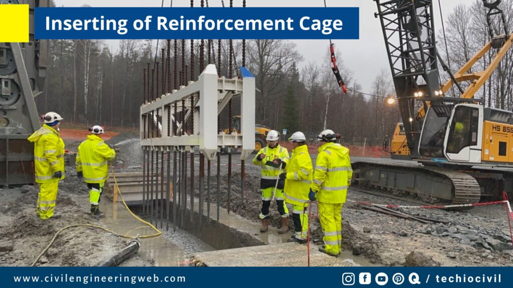
4. Inserting of Reinforcement
In this stage, Reinforcement cage of diaphragm wall is inserted into the trench by the help of crane.
5. Concreting
After the excavation of panels and inserting of reinforcement cage, the trench is filled with suitable concrete mix by the help of tremie pipe.
Method of diaphragm wall construction
Diaphragm walls are constructed by two or more than two ways, But here we discussed two mostly used method of diaphragm wall that is listed below.
- Successive Panel Method
- Alternate Panel Method
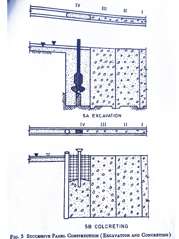
1. Successive Panel Method
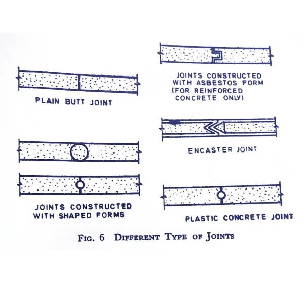
In this method a panel shall be cast in continuation of previously completed panel, so as to form a good joint and a continuous leakproof diaphragm wall.
Excavation of each trench panel shall be done with the help of suitable machinery. The trench panel shall be kept filled with bentonite slurry of suitable consistency and viscosity during the excavation period.
A stop end tube with a smooth surface, or a structural section shall be inserted in the trench at the end of the panel to support concrete and to form a suitable joint with the next panels.
Reinforcement cage shall then be lowered in the trench panel and suitably supported. The concrete cover for the reinforcement shall be maintained by the use of spacers.
Boxes or inserts for formation of recesses or for ground anchors shall be lowered along with the case to correct position and levels.
The end tube shall be taken out gradually after initial set of concrete. This may be done carefully with the help of a suitable crane or any other lifting device. Withdrawal of end tube should not cause any cracks in concrete at the panel end.
Also Read: What is Corrosion of Reinforcement
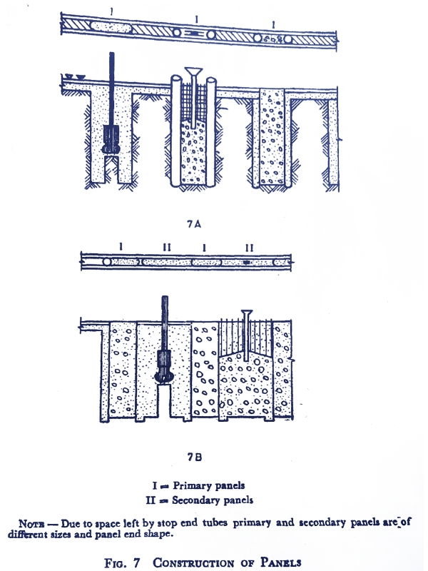
2. Alternate Panel Method
In this method Primary Panels shall be cast first leaving suitable gaps in between. Secondary panels shall then be cast in these gaps (see image).
Two stop end tubes are used at the ends of the primary panels to support concrete and to form suitable joints with the secondary panels.
The excavated length of trench for secondary panel may be smaller than that of primary panel. The shape of the secondary panel end should be such as to form a good joint with primary panels.
The other construction techniques shall be similar to those in the successive panel method.
Reference: IS: 9556 – 1980 Design and Construction of Diaphragm Walls
Hydromill Module SH 50 Diaphragm/Slurry walls Soilmec [150m & 250 mt deep]
Diaphragm walls are common practice in civil engineering as part of or as aids to the building of civil and hydraulic structures. Info on Soilmec Hydromill Module SH-50: https://goo.gl/oC9drn Mounted on Crane Tiger SC-135: https://goo.gl/B69u0K Basically, a trench is excavated in the ground, generally in the presence of a stabilizing fluid, and it is then back-filled with an appropriate material. The material is cut and loosened with two cutting wheels mounted at the bottom of a steel frame and rotating in opposite directions. Mud treatment unit SMT-500: https://goo.gl/8B1q16 The loosened or cut material mixes into the bentonite slurry suspension which is pumped from the trench by a very powerful suction pump mounted on the hydromill and conveyed to a mud treatment unit plant for cleaning. Hydromill offers a greater rate of penetration for the excavation than most any other type of diaphragm wall technique and also offers the highest level of accuracy in verticality. Supports and pre-escavation: SC-70 https://goo.gl/0UuTFA Il modulo idrofresa SH 50 è costituito da un robusto telaio in acciaio sul quale sono montati due unità di perforazione contro-rotanti e indipendenti. Con l’obiettivo di correggere la deviazione dalla verticale sono state progettate sulla superficie del modulo fresante delle alette mobili indipendenti. Soilmec ha sviluppato un sistema di rotazione del modulo fresante per la realizzazione di pannelli a T in quanto in cantieri con poco spazio disponibile la variazione dell’orientamento della macchina può essere un’operazione molto difficile portando a un notevole aumento di costo e di tempo di realizzazione dell’opera. Follow us on Facebook: https://www.facebook.com/Soilmecspa Subscribe on our YouTube channel: https://www.youtube.com/subscription_center?add_user=SoilmecSpa Follow us on Twitter: https://twitter.com/SoilmecSpa
I am a Professional Civil & Structural Engineer having more than 4 years of experience in Engineering, Procurement and Construction industry. Here i sharing the latest updates of EPC Projects and Construction News.