
In this article, we share the complete details regarding load combinations as per ASCE-7, ACI 318, EN 1990 and other English standard for concrete design.
Before going to know the various load combinations of concrete design as per English code, lets understand the what is load combination in short.
Basically, Load combination is a sets of different load cases that are acting together on a structure in various situation. It is used to check the stability of structure in worst case of loading situations.
Here are the few load combinations based on Euro, English and British codes.
Table of Contents
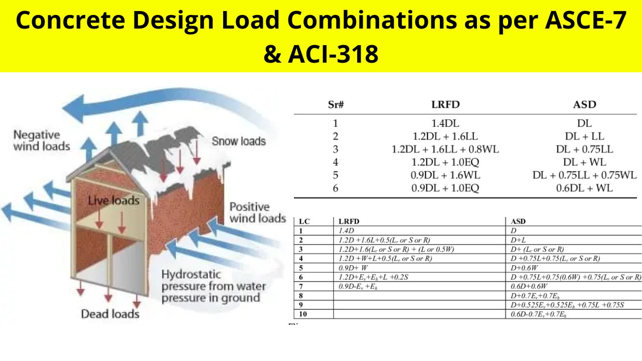
Load Combinations as per ASCE-7
Also Read: Load Combination as per IS 456
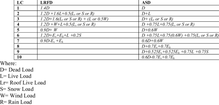
Load combination for Load and resistance factor design
- 1.4D
- 1.2D+1.6L+0.5(Lr or S or R)
- 1.2D+1.6(Lr or S or R)+(L or 0.5W)
- 1.2D+1.0W+L+0.5(Lr or S or R)
- 1.2D+1.0E+L+0.2S
- 0.9D+1.0W
- 0.9D+1.0E
Load combination for Allowable stress design
- D
- D+L
- D+(Lr or S or R)
- D+0.75L+0.75(Lror S or R)
- D+ (0.6W or 0.7E)
- D+0.75L+0.75(0.6W)+0.75(Lr or S or R)
- D+0.75L+0.75(0.6E)+0.75S
- 0.6D+0.6W
- 0.6D+0.7E
Where,
- D = Dead Load
- L = Live Load
- Lr = Live Load
- W = Wind Load
- E = Seismic Load
- R = Rain Load
- S = Snow load
Also Read: Different types of load on Building
Load Combination as per ASCE-7 (05)
Load combination for Load and resistance factor design
- 1.4(D+H)
- 1.2(D+F+T)+1.6(L+H)+0.5(Lr or S or R)
- 1.2D+1.6(Lr or S or R)+(0.5L or 0.8W)
- 1.2D+1.6W+0.5L+0.5(Lr or S or R)
- 1.2D+1.0E+0.5L+0.5(Lr or S or R)
- 0.9D+1.6W+1.6H
- 0.9D+1.0E+1.6H
Load combination for Allowable stress design
- D
- D+L+F+H+T+(Lr or S or R)
- D+(W or 0.7E)+L+(Lr or S or R)
- 0.6D+W+H
- 0.6D+0.7E+H
Where,
- W = Wind Load
- E = Seismic Load
- F = Fluid Pressure
- R = Rain Load
- S = Snow Load
- T = Temperature Force
- H = Horizontal Pressure
Also Read: Roof truss Wind load calculation as per IS 875-2015
Load Combinations as per ACI 318
Load combination for Load and resistance factor design
- 1.4(D+F)
- 1.2(D+F+T)+1.6(L+H)+0.5(Lr or S or R)
- 1.2D+1.6(Lr or S or R)+(1.0L* or 0.8W)
- 1.2D+1.6W**+1.0L*+0.5(Lr or S or R)
- 1.2D+1.0E***+1.0L*+0.2S
- 6. 0.9D+1.6W**+1.6H
- 7. 0.9D+1.0E***+1.6H
Where,
- D = Dead Load
- L = Live Load
- Lr = Live Load
- W = Wind Load
- E = Seismic Load
- F = Fluid Pressure
- R = Rain Load
- S = Snow Load
- T = Temperature Force
- H = Horizontal Pressure
Live Load Reduction in buildings except Garages, Public Assembly, and area that has 100 lb/ft2 of live Load. *1.0L can be reduced to 0.5L.
Wind load reduction in load combination where W is not reduced by directional factor as per ASCE 7-02 (Wind Calculation): **1.6W can be reduced to 1.3W.
*** 1.4E Shall be used instead of 1.0E When seismic load E is calculated based on service load.
Also Check: Things To Consider When Using Suspended Loads
Strength Reduction Factor as per AIC 318
If the structural framing includes primary members of other materials proportioned to satisfy the load factor combinations in Section 2.4 of ASCE 7, it shall be permitted to proportion the concrete members using the set of strength reduction factors listed in Appendix C and the load factor combinations in ASCE 7.
- Flexure without Axial Load : 0.9
- Axial tension, and axial tension with flexure : 0.9
- Member with Spiral Reinforcement : 0.75
- Other Reinforced member : 0.70
For More Strength reduction factor, please refer AIC 318

I am a Professional Civil & Structural Engineer having more than 4 years of experience in Engineering, Procurement and Construction industry. Here i sharing the latest updates of EPC Projects and Construction News.