
In this article, we explain method of design, what is working stress method, limit state method, and ultimate load method. difference between working stress method and limit state method. please read the article till the end.
Table of Contents
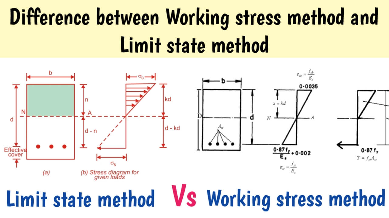
Difference between working stress method and limit state method.
| Working stress method | Limit state method |
|---|---|
| It is based on IS: 800. 1984. | It is based on IS: 800 – 2007. |
| It is called an Allowable stress method (ASM) or Elastic design method. | It is also called as plastic design method. |
| Allowable stress is within its range of elastic limit. | Partial Safety Factor (Ymo) is used for Yield Stress and Partial Safety Factor (Ym1) is used for Ultimate Stress. |
| Analysis of the structure is done by the working load. | Working load is factorized by partial safety factor (YF). Analysis of structure done by factored load. |
| Working load does not yield or buckle the material. | The behaviour of the material after yield plays an important role in determining the capacity of the material. |
| Deformation is calculated from working load. | Deformation is calculated from the working load. |
| Serviceability and economy not taken in consideration during design. | Serviceability and economy are taken into consideration. |
| It give heavy design. | It offers lighter sections. |
| Fatigue and fire resistant not taken in calculation | Fatigue and fire resistance are taken into account. |
Method of Design:
- Working stress method
- Ultimate load method
- Limit state method
1. Working stress method:
Working stress method is the first discovered design philosophy. This philosophy was traditionally used not only for the design of steel structures but also for the design of concrete structures.
Working stress method is also known as elastic method or modulus ratio method or factor of safety method.
In this method, it is assumed that the structural material behaves elastically and due to working loads (service loads) the stress has within its limit and a proper factor of safety can be achieved.
In the case of working stress method, the area and moment of inertia of that member is determined in such a way that the stress developed is less than the allowable stress or permissible stress.
Allowable stress, in the range of elasticity and yield stress is less than fy.
Allowable stress = 0.6 fy
Design load in RCC = Working or service load.
Design stress or permissible stress = characteristic strength of material / factor of safety.
M20 = fCK = 20MPa
Factor of safety in beams:
Concrete = 3
Steel = 1.78
In working stress method, design load is based on uniqueness theorem, design strength of material is based on lower bound theorem.
In this method, serviceability is not considered.
Best books for Design of Steel Structure.
2. Ultimate load method:
This method is also called ‘plastic design’ or ‘ultimate load method.
Design load in RCC = Ultimate or collapse load
= working load or service load × load factor
Load factor depends on load combinations.
Design or permissible stress = characteristic strength of material / factor of safety of material
Material factor of safety in beams :
Concrete = 1.5
Steel = 1.15
In ultimate load method, design load based on upper bound theorem and strength of material based on lower bound theorem.
In this method, serviceability is not considered. Therefore it has not become popular.
Cheapest and best book for Design of Steel Structure.
3. Limit state method:
The design philosophy of Limit state method (LSM) is more advanced than other traditional design philosophies.
In Working stress method, calculations are done with working load and in Ultimate load method, calculations are done with ultimate load. But in Limit state method, ultimate load is taken for ‘safety‘ and working load is taken for ‘serviceability’.
What is a ‘limit state’?
The acceptable limit for the safety and serviceability requirements before failure occurs is called a limit state.
Limit state method is divided into two parts:
- Limit state of Strength
- Limit state of serviceability
1. Limit state of strength:
Limit state of strength is associated with protect failure of the structure and loss of life and property when the worst load combination appears on the structure.
The main types of limit state of strength are as follows:
- Loss of equilibrium of the structure
- Loss of stability of structure
- Failure by excessive deformation or rupture
- Fracture due to fatigue
- Brittle fracture
2. Limit state of serviceability:
Limit state of serviceability is associated with satisfactory performance of the structure during working load.
This type of limit state is associated with the comfort of the people living in the structure.
The main types of limit states of serviceability are as follows
- Deflection
- Fatigue
- Vibration
- Fire resistance
- Durability
1. Deflection:
Excessive deflection causes problems such as insecurity, cracks in the plaster, damage to the finishing, disalignment of plant and machinery, reduction in the strength of the structure.
Deflection is mainly checked for the worst combination of service load.
2. Fatigue:
Fatigue limit state is important when stress is increasing due to repeated loading on the structure. Fatigue is important for bridges, crane girders, vibrating machinery platforms, etc.
Fatigue is considered the ultimate limit state, but fatigue checks are done with a working load.
3. Vibrations:
As the use of lightweight construction and longer spans increases, the risk of vibrations increases. When vibrating load is felt on the platform due to vibrating machinery or crane, it is necessary to check the vibration. Activities like dancing, marching, drilling, shock load also produce vibrations.
4. Fire resistance:
The fire resistance of a steel structure depends on its strength, geometry, action on it, support conditions, type of fire and protection against fire.
5. Durability:
A structure is said to be durable if it performs the required functions, expected environment and exposure conditions during its prescribed lifespan.
Factors affecting the sustainability of buildings are as follows:
- Environment
- Degree of exposure
- Shape of the member
- Structural detailing
- Ease of maintenance
Design load/Ultimate/Collapse/Limiting load RCC:
FD = CHARACTERISTIC LOAD × Yf
FD = F × Yf
Yf = Partial safety factor for loads (IS-875, P-5)
Gate material for Design of Steel Structure
Characteristic load:
The load which has 95% probability of not being exceeded in the life of a structure is characteristic load.

Fm = average / mean load.
F = Fm + k(s)
F = Fm + 1.65 (s)
F = Characteristic load
Fm = (F1+F2+F3+….) / n
s = standard deviation,
s = (((Fm-Ft)2) / (n-1))0.5
Note:
- RCC limit state is based on 95% probability load.
- Pavement design is based on 98% probability load.
The live loads acting over a structure at different conditions are given below, determine characteristic load.
30kN/m, 15kN/m, 20kN/m, 45kN/m, 50kN/m
Fm = (30+15+20+45+50) / 5
= 32kN/m
As per IS 456, to have characteristic, min 30 sample are required to have proper correlation.
S = ((32-30)2 + (32-15)2 + (32-20)2 + (32-45)2 + (32-50)2 /(5-1))0.5
= 15.24
Characteristic load, F = 32 + 1.65 × 15.25
= 54.16kN/m
In case of earthquake load, replaced Wind load with Earthquake load in the combinations for partial safety factor Yf.
Both wind load & earthquake load occurring critically together is impossible, i.e why they are not considered together.
Question : Calculate design load in collapse and serviceability separately for:
- Dead load = 150kN/m
- Live load = 250kN/m
- Wind load = 25kN/m
- Earthquake load = 32kN/m
Design load for collapse:
1. 1.5 DL +1.5 LL = 1.5( 150+250) = 600Kn/m
2. 1.5 D.L +1.5 E.L = 1.5 ( 150+32 ) =273Kn/m
3. 1.2 ( D.L +LL+EL) = 1.2( 150+250+32 ) = 518kN/m
Use maximum of three values = 600kN/m
Design load for service:
1. DL+LL = 150+250 = 400
2. DL+EL = 150+32 = 182
DL + 0.8LL+ 0.8EL = 150 + 0.8(250+32) = 375.6KN/m
Service design load = 400kN/m

I am a Professional Civil & Structural Engineer having more than 4 years of experience in Engineering, Procurement and Construction industry. Here i sharing the latest updates of EPC Projects and Construction News.